We worked with Civil Engineers to define the building and the layout of MATHUSLA at P5. The layout is restricted by the existing structures based on current concept and engineering requirements.
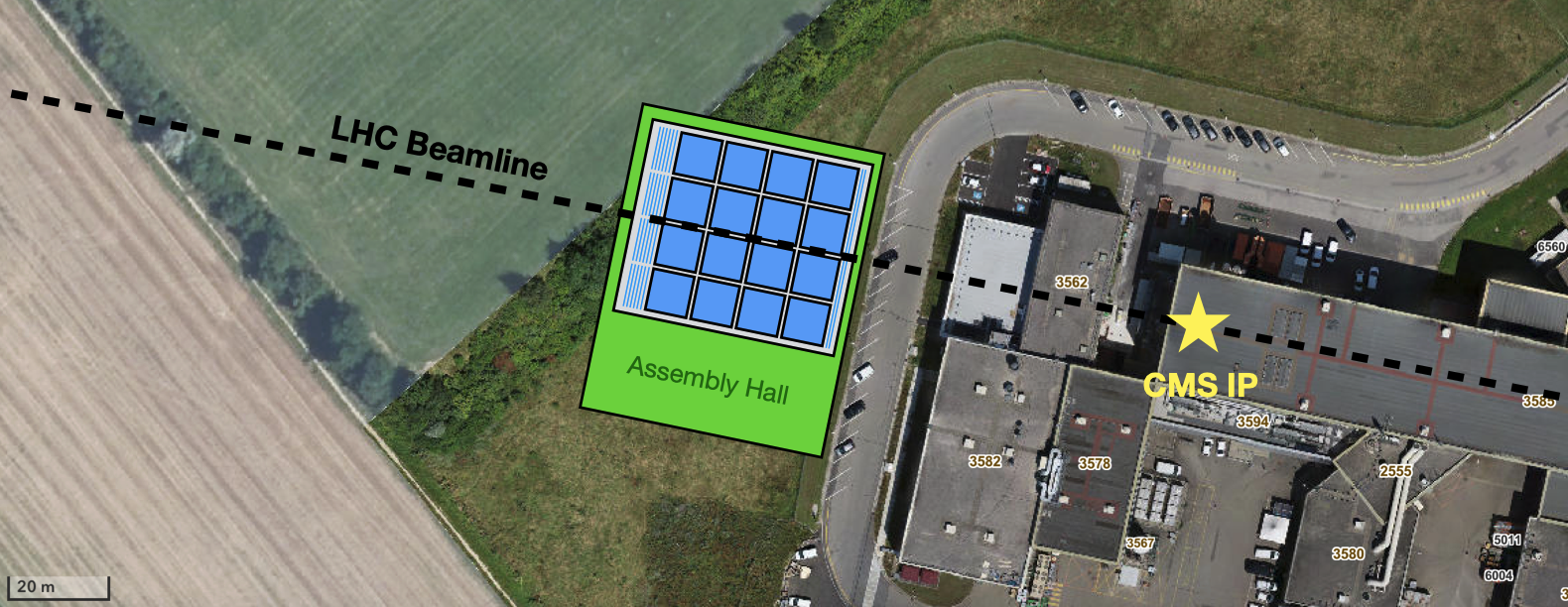
The current layout fit the available land around CMS that is already CERN property. MATHUSLA is located 70-110 m horizontally to the CMS beam axis and 82-93 m vertically above it.
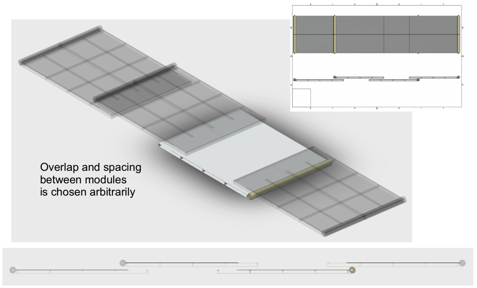
The main detector is subdivided in modules with a size of around 9 m x 9 m with a height of ~4 m. This permits staging the construction.
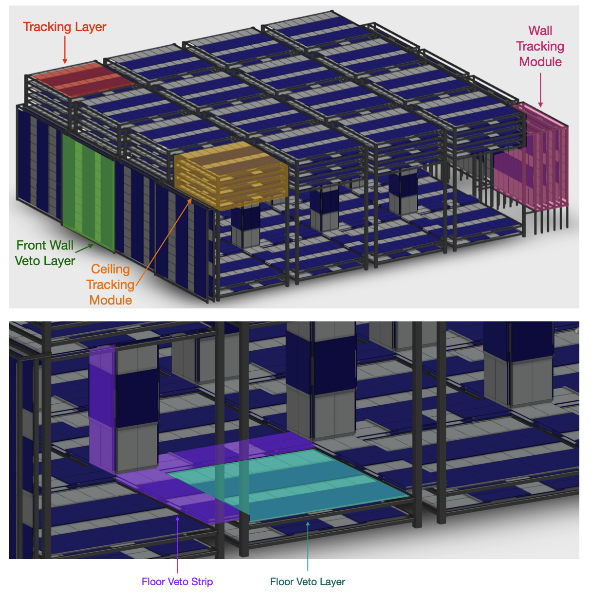
and 1 m above the floor in the tower modules, as well as ∼2.3 m × 9 m floor veto strips, which cover the gaps between tower modules. Four vertical floor veto strips also each constitute a single column detector,
instrumenting the vertical support columns. In combination, this veto detector system is hermetic for LHC muons and downward cosmics.
Each tracking module, to be installed in the ceiling or rear wall, is comprised of 6 tracking layers with an area of ∼(9 m)^2, separated by 80 cm for a total height of 4 m. Each ceiling tracking module is mounted in a tower module with four vertical supports, which also support the components of the floor veto detector. Tower modules are arranged in a 4 × 4 grid to cover the entire decay volume, and are separated by 1 m-wide gaps. The gaps have little impact on signal efficiency but are crucial for allowing maintenance access. The rear wall tracking modules are similarly arranged in a row with 1 m gaps between them.
The 6 tracking layers in each tracking module are comprised of scintillating bars of 3.5 cm width that are arranged with alternating transverse orientation to their neighboring tracking layers. This configuration provides position and timing coordinates of charged particles resulting from the decay of LLPs in the MATHUSLA detector decay volume with∼1 ns timing and∼cm transverse spatial resolution. The tracking layers in each tracking module on the ceiling or wall are also used as trigger layers in addition to providing tracking information. Having six tracking layers ensures that an ideal track has 3 hits with high spatial resolution along each coordinate. The number of layers was also optimized with full simulations to ensure the primary physics target LLP signals can be searched for with effectively zero background, even if a single tracking layer fails in parts or the entirety of the detector. All the tracking layers at a given height or horizontal distance from the rear wall constitute one tracking plane.
Each of the two layers of the front wall veto detector is implemented by a slightly staggered arrangement of four (11.2 m)^2 front wall veto layers to provide hermetic coverage for the full 40 m width of the front wall. The bars in each layer are oriented perpendicular to each other to provide ∼cm spatial resolution for particles that hit both layers. The floor veto detector is comprised of floor veto layers and floor veto strips. The floor veto layers are identical to tracking layers in the tracking modules, and are mounted at heights of 0.5 m and 1m above the floor in the tower modules to cover the majority of the floor area. Floor veto strips have physical dimensions of 9 m × 2.8 m and each provide about 9 m × 2.3 m of double-layer sensor coverage. They are are mounted horizontally above the floor veto layers to cover the gaps between tower modules, and are also mounted vertically around the support columns to constitute column detectors that enclose the space at the corners of the tower modules. In addition to making the floor detector hermetic with respect to cosmics, these column detectors also provide explicit material veto capabilities for inelastic cosmic ray interactions in the support column.
Here some drawings showing the sub-module units.
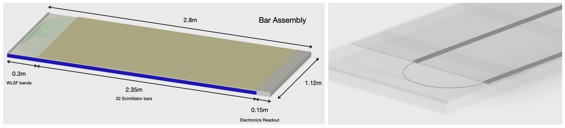
the WLSF ”bends” as the fibers go down one bar and back through another bar. In this way all SiPMs for the bar assembly are on the same end. Right: details of the WLSF bend region.